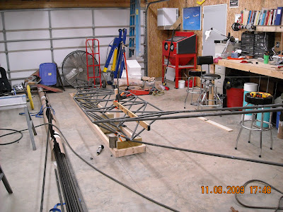
Sunday, November 8, 2009

The longerons going to the tail are telescoped down in size. The rule is, you need to have a 30 degree angle cut into the receiving tube and at least 1 1/2 diameters worth of the smaller tube must be in the receiving tube. For example the large tube is 7/8"x.058 and a 3/4 tube goes inside it. The 3/4" tube must have at least 3 times 3/4" (2.25") completely inside the 7/8" tube. Below I am welding up the splices. I use the block of steel to hold it until I tack it, then just roll it as I weld.


Now, I set the spliced longerons into position and tack them to the forward fuselage.


The tail area is tacked into position. A block of wood with two holes drilled in it is used to hold the tubes in place. I drilled the block of wood such that I could use it to place a level on it and level everything up. Also shown is a simple way to use a carpenters square to square up and hold everything in position. From here, I simply add the cross tubes.


The tubes in the back are left long and will be trimmed later.


Once all the tubes in the forward fuselage were put in, I spent several hours completely welding all the joints. This was done in a quasi spiral fashion which balances out the stresses of  welding and minimizes distortion.

Now I had to get ready to jig up the tail but it is 46 inches above the centerline of the bottom tube. Since that would put it out of reach if I left it on the table I moved the ultra simple jig to the floor and re-leveled it.


Notice that it only takes a simple stick clamped to the fuselage to hold it into position.


I now cut out a jig similar to the others out of a scrap piece of plywood and mount it to a 2x4 which I clamped to my table. The table was placed the exact distance away to place the jig in the proper position. I used strings and a plumb bob to line everything up. Below, I am attaching the centerline string and then drop a plumb from the centerline of the jig to help align it all.


I am using a super simple jig for the Breezy. Below is a jig that my friend Gary Angelo and I made to weld up One Design fuselages. This jig is intended to be able to build several fuselages and to hold close tolerances. I also am using a TIG welder to do all of the welding whereas I am using my trusty J40 Victor on the Breezy. The TIG does beautiful welds but I always felt the need to go back and stress relieve the clusters even though several manufacturers (like the Pitts factory) TIG welds with no stress relieving.


The point is, you make the jig to fit the project. The Breezy doesn't require an elaborate jig to get the job done. Essentially, you make sure that a few key stations are in the right position and then you fill in the space in between. All the tubes in between just need to be reasonably close as they only transfer the load. This is an important concept that new builders need to understand. Know when you need to be really accurate and know when you don't. This will save you tons of time and allow you to make real progress. I've seen people get really anal retentive about jigging and/or making ultra precise layouts for parts that don't need it. However, please don't confuse this with good workmanship. Always make your parts in a craftsman like fashion.

Here is the "jig" with the strings. The strings really let you spot anything that is even a fraction of a millimeter off.


Next, I'll start adding tubes...

Saturday, October 31, 2009


Here you can see that most of the tubes are tacked into place. Everything has been checked and triple checked for straight and square.


Installing the front steering tube:


I couldn't find both 2"x.058 and 1 7/8"x.058 tubing so I had to go to the next smaller size. The smaller tube goes into the larger tube and rotates to provide steering. I checked with Wicks, Aircraft Spruce as well as many smaller metal supply places and just could not find any 1 7/8x.058. A quick look at the "load allowables" table shows that a smaller tube can easily handle the loads.

The tube is angled back 18 degrees and that is pretty easy to establish however, getting the angle right as well as centered and absolutely vertical is a little tougher. Below shows how I accomplished this. I placed a carpenters square on the last plywood jig making sure it is perfectly aligned with the centerline and squared with the top. I then placed a long tube in the front, stood back and sighted down to compare the long tube with the carpenter square.


This shot shows how easy it is to get very accurate alignment. Using this method you can get extremely precise in the vertical alignment as well as the centerline.


By welding the tubes to the side of the front tube, it allows a little more room to move the rudder pedals forward a slight bit. Carl Unger and his co-designers were apparently leg length challenged. I'm 6'2" and ummm...husky, so I need just a tad more leg room. On a side note, I increased the length between the forward stations by a few inches for a total stretch of 7 inches. This will give the passenger a little bit more leg room  and allow the front seater to not be hitting his knees on his chin. I haven't decided yet if I will add back seat controls but this will make it easier to position them if I do. However, even a small stretch has consequences. But with very simple mathematics we can easily move the large, heavy weight we call an engine, back a couple of inches to compensate. I want to keep this as minimal as possible as the Breezy is a well balanced flying machine as is. Others have done an even longer stretch and it doesn't seem to affect the flying qualities so I should be in good shape. The other negative to any change is that it will invariably add weight. A lighter airplane will always perform better but I feel this change is minimal enough to be well worth it.


Just about time to start welding in earnest!!

More fitting and tack welding

more fitting and tack welding...


This is about as close as you have to fit the tubes. On the lower part of the joint I can just slip a 1/16th welding rod in at the widest gap. You can get by with a slightly larger gap occasionally but if your fit is a lot worse than this you probably need to take it out and redo it. Even if it is tack welded, it's very easy to grind off the tack weld and pull the tube out. You can almost always find a place where you need a slightly shorter tube and then use the removed tube after you cut off the end.


I placed all of the diagonal braces where I could...


Here I used a clamp to hold the tube in place while I tack the bottom. Then I can remove the clamp and tack the top of the tube.


Eventually, I had to remove the plywood jigs so I could place the remaining tubes. You can now see why I placed slots in the plywood... I only remove one station at a time and fit and tack the tubes at that station. That way, you can keep everything straight and true. Once we start welding, things will start to move around, sometimes quite dramatically. However, by staggering the joints when we weld (skipping around and not welding consecutive stations on the same side) we can mitigate this almost completely. Also, keep in mind that as long as the wing, tail and engine are in reasonable alignment with regards to each other, it doesn't really matter how the rest of the fuselage sits. You could be sitting in the seat listing thirty degrees to the port and the plane would fly just fine. But since aesthetics is important we will try to keep everything nice and straight!


My son is a sophomore at Vanderbilt and he always helps me out when he visits. He is actually building me a shelf/stand for the small refrigerator he got me for the shop for my birthday! He's got quite a bit of experience now building various things. He's done composite work on some aircraft parts, helped me build the shop, helped build a wood fired pizza oven, built a recumbent bike and helped me put a Chevy 350 engine in a Datsun 280z car amongst other smaller projects. He is a great help and I love working with him.


I constantly keep checking level at all stations. Now is the time to slightly tweak the frame while putting in the diagonals. All of these extra tubes are what locks in the shape of the frame.


Friday, October 30, 2009

Fitting the tubes....
Cross pieces are put in first to establish the stations. Then verticals are placed using a plumb bob to make sure they are exactly vertical. Of course, on the stations that have a plywood jig, I use that to establish the vertical.


Below is a little time saver. I used some scrap aluminum (cardboard would probably work better) to make a pattern since there were quite a few of the same cut on the 7/8ths inch tubes. Just place it around the end of the tube and use a silver pencil or sharpy to trace the pattern.


I tack each tube in as I go since this type of simple jig is not intended to hold each and every tube.